Construction Equipment Visibility
Posted on by
Road construction workers face many hazards on the job. In addition to many of the hazards present on a “traditional” construction site, road workers also need to contend with moving vehicles both in and around the job site. Road construction workers risk injury from construction equipment operating within work zones. From 1995 through 2002, 844 fatal occupational injuries occurred at road construction sites. The majority of these fatalities, 693 (82%) cases, were reported to be transportation incidents. Fatalities involving a ground worker being struck by a vehicle or equipment accounted for 509 (73%) of the transportation incidents. Victims were as likely to be struck by construction equipment (32%) as by highway vehicles (28%). Backing up accounted for at least 50 percent of fatalities from being run over by construction equipment [Pegula 2004].
In 2001, NIOSH began developing and evaluating interventions to reduce the number of ground workers being struck by road construction equipment. While developing evaluation methods, researchers created equipment blind-area diagrams. Although originally developed for use by NIOSH researchers, industry stakeholders suggested that blind-area diagrams can be a valuable training resource for road construction companies and labor unions. This information can be useful to companies when purchasing new vehicles. Additionally, educating drivers and road crew about vehicles’ blind areas can help to reduce related injuries and fatalities.
What Is a Blind-Area Diagram?
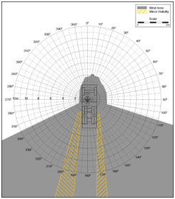
A blind-area diagram is best described as a drawing that depicts the area around a vehicle or piece of equipment that cannot be seen from the operator’s position. The blind-area diagrams utilized the procedure outlined in [ISO 5006:2006], “Earth-moving machinery – Operator’s field of view – Test method and performance criteria.” This procedure uses light sources to represent the operator’s eyes and the shadow created by blockages associated with the vehicle, such as door posts and mufflers, to represent the blind area.
NIOSH had blind-area diagrams developed for three different planes: ground level, 900 mm (36 inches) above ground, and 1500 mm (59 inches) above ground. The blind area associated with each plane corresponds to the area at which an object on that plane cannot be seen from the operator’s position. The 900 mm plane was chosen because it represents the height of a construction barrel. The 1500 mm plane is slightly less than the shoulder height of 95 percent of the US adult female population, representing the height at which enough of the head is visible for an operator to recognize a person.
How Can Blind-Area Diagrams Be Used in Training?

Blind-area diagrams of 38 pieces of construction equipment and 5 pieces of mining equipment are available on the NIOSH website. These diagrams may be downloaded as visual aids for demonstrating the hazards of working around operating equipment to field crews during classroom training sessions or as the basis for toolbox talks held in the field. The diagrams may also be printed at a scale that matches scale models of equipment. This shows the size of blind areas relative to the equipment, as shown in Figure 1.
Blind-area diagrams can also be used to understand how equipment selection can influence the risk to workers around operating equipment. Though only a limited number of blind-area diagrams are available, the website does provide diagrams for a wide range of equipment types. Studying these diagrams can help construction companies understand the primary obstructions (e.g., mufflers, engine cowlings) creating blind areas. When considering equipment for purchase, companies can use this understanding to select equipment that provides operators with the best possible visibility.
What Next?
NIOSH published these blind-area diagrams on its website, contributed to worker training programs and trade journal articles, and enlisted roadway construction industry partners to promote the distribution of these diagrams. NIOSH is interested in learning
- The extent and manner that these diagrams are being used in the roadway construction industry
- The applicability and extent of use of these diagrams in other industries
- How these diagrams might be used to promote awareness of blind areas around construction equipment and reduce the number of workers struck by operating construction equipment at construction sites.
- How best to provide this information to the jobsite
We value your input and assistance in preventing worker injuries. For more information about work zone safety, refer to the highway work zone topic page. For more information about our research in construction safety and health, please refer to our construction program page.
Mr. Fosbroke is a statistician with the Division of Safety Research, Surveillance and Field Investigations Branch. His research focus is on preventing worker injuries in roadway construction work zones and includes secondary data analysis of occupational injuries and illnesses, engineering evaluation of construction equipment visibility, field evaluation of interventions, and partnership with roadway construction industry employers, labor unions, transportation agencies, and academic institutions to promote work zone safety for workers and road users.
Sources
- Pegula, SG [2004]. Fatal occupational injuries at road construction sites. Monthly Labor Review 12:43-47.
- ISO 5006:2006 “Earth-moving machinery – Operator’s field of view – Test method and performance criteria.”
Posted on by

